A wall lights specification is decided by six inputs, not by a catalogue photograph: the wall function (corridor, stairwell or facade), the output direction (up, down or both), the mounting height and spacing set by the architecture, the voltage and control arrangement on site, maintenance access, and the acceptance checks the installer will be measured against. Settle those six before you request quotations, and a later change becomes a drawing revision instead of site rework. The sections below follow the order we use when a design studio or fit-out contractor sends us a wall-lighting enquiry. The wall lights we manufacture to order are built at our Guzhen, Zhongshan factory to your dimensions, material and finish, so each unit can be made to your specification.
Up, Down, or Up-and-Down Output
Output direction is the first and most frequently under-specified line item on a wall lighting schedule. A down-only fitting throws light onto the floor and onto the wall immediately below the bracket. It is the default for circulation routes because the upper wall stays dark, which reads as calmer at eye level and reduces the number of lit surfaces a cleaner has to wipe.
An up-and-down unit sends a second beam up the wall. That upward wash lifts the apparent ceiling height and gives a corridor its rhythm, which is why guest corridors and lift lobbies so often end up specifying it. The trade-off is glare and maintenance, not output. An upward beam shows every irregularity in plaster, drywall joints and cladding seams, so it only belongs on walls finished to a proper standard. It also collects dust on the lens and on the top face of the bracket, which raises cleaning frequency. If the wall above the fitting is unpainted blockwork or carries surface conduit, choose down-only.
| Output direction | Typical application | Effect on the wall | Main risk to manage |
|---|---|---|---|
| Down only | service corridors, back-of-house, exterior doorways | pool of light at floor level, upper wall stays dark | visible hot spot if the bracket is mounted too high |
| Up and down | guest corridors, lift lobbies, feature facades | symmetrical scallops above and below the fitting | upward beam reveals wall defects |
| Up only | accent walls behind joinery, wall washing | soft gradient rising to the ceiling | no useful light at floor level |
On corridors longer than roughly 20 m, alternating up-and-down fittings with down-only units between them keeps the rhythm readable while avoiding an over-lit wall.
Mounting Height and Spacing: How to Derive Both
Setting the mounting height
Work from finished floor level, not from the structural slab, and state that on the drawing. For a down-only fitting in a standard 2.7–3.0 m corridor, a bracket centreline between 1.8 m and 2.1 m above finished floor keeps the light pool on the floor and away from head height. If the unit also throws upward, leave at least 300 mm of clear wall between the top of the bracket and the ceiling, otherwise the upward beam produces a compressed scallop that reads as a mistake. In double-height spaces, mount lower and increase the upward throw rather than lifting the fitting, because a high mounting position puts the bright aperture into the sightline of anyone walking towards it.
Setting the spacing
For down-only units, centre-to-centre spacing of roughly two to two and a half times the mounting height above finished floor gives even pools without dark bands between them. In practice the architecture should override the arithmetic: divide the corridor length by the door, panel or tile module and use the nearest value that lands the fittings on module lines. A schedule that says “every 3.6 m” across a 5.4 m run will always produce an awkward half space at one end. Where a corridor also carries a continuous ceiling light run, set the wall units to the same module so the two rhythms read as one system.
Stairwell Lighting: Illuminance, Glare and Tread Visibility
Stairwells are the one place where a wall light has a safety job as well as an architectural one. The design target is a clearly readable tread edge on every step, viewed from both directions of travel.
Three rules cover most flights. First, light the treads rather than the void: mount down-only fittings on the wall beside the flight, between 2.0 m and 2.2 m above the pitch line, so the beam lands on the nosings instead of the landing soffit. Second, keep the aperture out of the downward sightline. Standing at the head of a flight, a guest should see the lit steps and never the bright lens; positions within about 30 degrees of the eye line at the top landing should be rejected. Third, treat landings and direction changes as separate zones, because a single fitting per floor, however bright, leaves the turn unreadable.
Where a stair passes through a glazed screen or sits against a light-coloured wall, reduce the number of wall units and add a low-level source at the base of the flight. That cuts the contrast between the lit wall and the shaded treads, which is usually the reason a technically adequate stairwell still feels unsafe to use.
Facade and Exterior Wall Lights: Rain and Voltage Design Considerations
Exterior wall lighting is usually specified at concept stage and then value-engineered at the wrong end. Two design considerations decide whether the installed result survives its first wet season: how water leaves the fitting, and whether the electrical arrangement matches the market it is shipped to.
Water has four routes into a wall-mounted exterior fitting: the lens aperture, the joint between the body and its removable cover, the cable entry, and condensation inside the body. Specify the aperture so that it faces downward or sits behind a shield, and avoid up-only units on exposed facades where water can stand on the lens. The cable entry should be at the lowest point of the body so that water runs away from the gland rather than into it. Ask for a replaceable gasket on every removable part, and for a drain path so that condensate leaves the housing. On coastal or high-wind sites keep the bracket shallow and the profile smooth: water driven sideways finds any horizontal ledge.
On the electrical side, confirm the destination voltage and frequency before tooling. A 120 V / 60 Hz installation and a 220–240 V / 50 Hz installation need different drivers and different terminal arrangements, even when the housing drawing is identical. Wide-input drivers that accept a broad AC range simplify multi-market purchasing, but voltage drop on a long facade run still has to be calculated: keep the drop within about 3 percent of supply and size the cable for the total load. Exterior wall lights are built to order for the destination market, with the driver and terminal arrangement fixed at the drawing stage.
Aligning Wall Lights with the Building Module
A wall light schedule that ignores the building module will be adjusted on site with a drill, and the result will be visible in every photograph of the finished space.
Set the centreline of each fitting on a module line: brick coursing, panel joints, tile joints, curtain wall mullions or the structural grid. Where a fitting falls between two module lines, move it to the nearest line and adjust the spacing of the whole run, rather than leaving a single unit 80 mm off module. The discipline applies vertically as well as horizontally.
| Building module | Alignment rule | What to check on the drawing |
|---|---|---|
| Brick or block coursing (about 300 mm) | centre the bracket on a course, not on a joint | course height measured at the mounting line |
| Panels or tiles (600, 1200 mm) | land the fitting on a panel, or at a joint for paired units | panel setting-out, including reveals |
| Curtain wall mullions | fix to the mullion, never to the glazing line | mullion size, finish and permissible fixing points |
| Structural grid | keep fittings on the same grid as the column faces | column face dimensions after finishes |
The fixing substrate matters as much as alignment. Blockwork, metal stud, precast panel and mullion each need a different bracket depth and fastener, and the wall light drawing should state the substrate assumed. If the substrate is unknown at design stage, ask for a bracket with a slotted base so the installer has adjustment in two directions rather than a drill and a problem.
Wall Lights Specification Acceptance Checklist
Use this list at drawing review before manufacture, and again at site delivery.
- Output direction recorded for every position (down only, up and down, or up only), with the reason stated.
- Mounting height measured from finished floor level and noted as such on the drawing.
- Spacing checked against the door or panel module, with the total run divided to avoid a short space at either end.
- Fixing substrate, bracket depth and fastener type stated, or a slotted base specified where the substrate is unconfirmed.
- Cable entry position confirmed at the low point of the body, with a drainage and gasket detail for exterior positions.
- Destination voltage and frequency listed against each order line, with the driver specified for that market.
- Finish agreed against a physical sample, including whether the surface is matte, satin or textured.
- Quantity checked with spare units for site damage, and spares shipped from the same batch for a finish match.
- Terminal arrangement and polarity confirmed, with a wiring diagram supplied alongside the delivery.
- Packaging checked for the transport mode: palletised for sea freight, individual cartons with corner protection for air freight.
Send Your Wall Lights Specification for a Made-to-Order Proposal
Wall lights for corridors, stairwells and facades are manufactured to order at ShineSculpt, so the specification above can be built into the product rather than worked around it. To come back with an accurate proposal on the first pass we need the drawings with the output direction marked at each position, mounting heights measured from finished floor level, the door or panel centres the run must follow, the destination voltage and frequency, quantities including spares, and a finish reference or sample. Cable entry position, market voltage and terminal arrangement are the three lines that generate most post-delivery queries, so it is worth confirming them before tooling starts rather than after delivery. Sketch-level drawings are enough to start; the fabricator-ready set can follow once the output direction and market voltage are agreed. Send the pack through our contact page or message us on WhatsApp at +86 180 2480 4499. We reply with a made-to-order proposal, a 15–30 day lead time, a 3-year manufacturer warranty and worldwide door-to-door shipping.
About the author : hy-tanya@hotmail.com

Related posts
Popular products
-
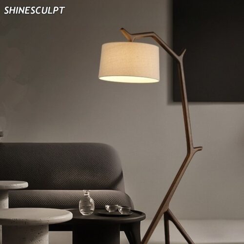 FL-013 Solid Wood Floor Lamp
Price range: $465.38 through $589.62
-
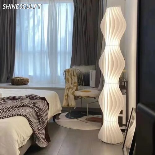 FL-012 Grass Skirt Floor Lamp
Price range: $34.62 through $62.31
-
 FL-011 Wabi-Sabi Floor Lamp
Price range: $500.00 through $576.92
-
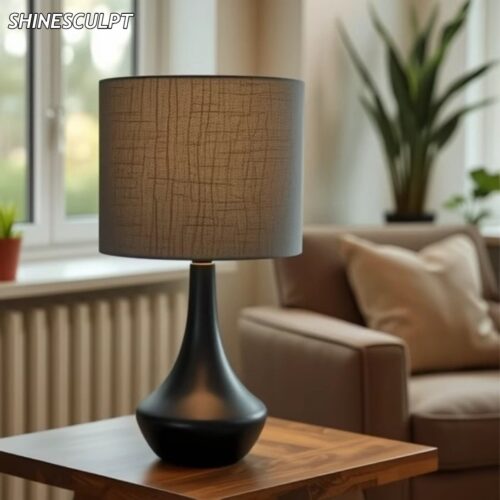 TL-006 Fabric Shade Bedside Lamp
$95.00